Place Freestanding Wall Unit Not Again Wall
Installation Guide - Featuring Multipiece Retaining and Freestanding Wall Systems
How to Apply This Guide
This guide is designed to provide you lot with ideas likewise equally information on product use and installation procedures. Because bodily project weather condition vary, final wall design, including the incorporation of geosynthetic reinforcement, must be performed by a qualified engineer. While this guide provides full general guidelines, installation contractors should refer to construction drawings provided past a qualified local engineer for final specifications. Additional installation information is available online at anchorwall.com. Information includes basic wall construction and installation videos.
BEFORE Y'all Brainstorm
Advance planning and conscientious layout at the job site help ensure a successful retaining and freestanding wall project.
• Review the site plan to ostend lot lines, wall location, length and elevations.
• Sympathise on-site soils. Ideal soils are sand and gravel. For walls built in clay or poor soils, work with a local engineer to ostend the wall blueprint and the required soil reinforcement. Blackness or organic soils should not be used as backfill.
• Ostend the location of underground utilities.
• Seek all necessary building permits.
• Prepare a cartoon of the site with the wall location, lengths and elevations.
• Programme drainage to forbid erosion or buildup of water behind the wall. Consider where the h2o volition drain through the wall, where downspouts volition expel and whether there's an underground sprinkler. For walls greater than 3 feet in elevation, a perforated drainpipe is recommended at the base of the aggregate to quickly remove big amounts of h2o. Run across page ix for more than information on h2o management.
• Check the block delivered to ensure information technology is the correct color. Check the geogrid to confirm that it'due south the strength and weight specified in the applied science plans.
• Be certain to apply the right tools. Hand tools include a shovel, 4-pes level, expressionless-accident hammer, 2- or iii-pound hammer, chisel, manus tamper, hydraulic splitter and string line. Power tools include a circular saw with a masonry blade and a compactor.
• Always habiliment protective eyewear.
Retaining Wall Nuts
Segmental retaining walls typically fall into 1 of three categories.
GRAVITY RETAINING WALL
The starting time category – a gravity wall – is a retaining wall that does not utilise soil reinforcement. A gravity wall has elevation limitations specific to each production. An advantage of this blazon of retaining wall is that it requires a smaller work expanse behind the wall. A gravity wall relies on the weight and setback of the block to resist the soil forces being exerted on the wall.
GEOSYNTHETIC-REINFORCED RETAINING WALL
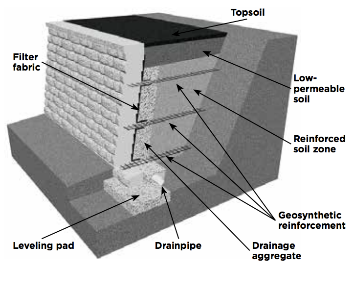
The second category is a geosynthetic-reinforced wall, which needs to be designed past a qualified engineer. In that location are (theoretically) no tiptop limitations with reinforced retaining walls, and they are used in larger applications. They require more work area behind the construction. The cake of soil is stabilized by introducing reinforcement layers into the soil mass behind the facing units. The larger the stabilized soil mass, the more soil can exist retained or held dorsum. The geogrid in the soil extends past the theoretical failure airplane and serves to create a large, rectangular mass of cake and soil, restraining the retained soil.
ANCHORPLEX™ Arrangement

The third category is the Anchorplex™ system, which offers a unique, nonconventional solution to problematic wall construction sites. It is a retaining wall built with Ballast™ products and structural backfill specified by Anchor Wall Systems, and backed by applied science support tools developed by Ballast. Employ of the Anchorplex system completely eliminates the demand for the structure of a mechanically stabilized world zone backside the wall facing and requires substantially less excavation than is commonly necessary in geosyntheticreinforced wall structure.
Retaining Wall Installation—Best Practices
Pale OUT THE WALL
• Have a surveyor stake out the wall's placement. Verify the locations with the project supervisor.
EXCAVATION
• Excavate for the leveling pad to the lines and grades shown on the approved plans and excavate enough soil backside the wall for the geosynthetic reinforcement material, if needed.
• The trench for the leveling pad should exist at least 12 inches wider than the cake you are installing and 6 inches deeper than the acme of the block. Encounter Diagram i

LEVELING PAD
• An amass leveling pad is made of compactable base cloth of iii⁄4-inch minus (with fines).
• The pad must extend at least 6 inches in forepart of and behind the start grade of cake and be at least 6 inches deep after compaction.
• If the planned form along the wall forepart will change superlative, the leveling pad may be stepped upwards in six-inch increments to match the grade change. Start at the lowest level and work upward whenever possible.
• Meaty the aggregate and make certain it's level forepart to back and side to side. Mist lightly with water earlier compaction. Run across Diagram 2

BASE Form
• This is the most important step in the installation process. Bury the base class of block.
• Begin laying block at the lowest tiptop of the wall. Remove the rear lip of the block by hit from the back and then that it will prevarication flat on the leveling pad.
• Place the get-go block level, front to back and side to side; lay subsequent blocks in the same mode.
• Place the blocks side by side, flush against each other, and make sure they are in full contact with the leveling pad.
• If the wall is on an incline, don't slope the blocks; step them upward so they remain consistently level. (Encounter page 7 for more data.)
• Use string line along the back edge of block to check for proper alignment.
• For multipiece products, use the largest unit, eighteen inches wide, for the base grade.
• Fill up cores (if applicable) and voids betwixt blocks with iii/4-inch free-draining aggregate prior to laying the next course of cake. Clean any debris off the meridian of the blocks. The Torpedo® base block is an option for walls upwards to maximum gravity superlative.
CONSTRUCTION OF SUBSEQUENT COURSES
• Clean whatsoever droppings off the superlative of the blocks.
• You can install these products using any combination of blocks.
• Identify the 2nd course of blocks on meridian of the base course. Maintain running bond. Pull each cake forward as far equally possible to ensure the correct setback. Run across Diagram 3
• Fill cores (if applicable) and voids between blocks with iii/4-inch free-draining aggregate prior to laying the side by side course of cake. Make clean whatever debris off the top of the blocks.
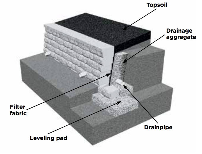
• For best results, use a filter fabric, which should be placed directly backside the wall extending from the lesser of the base of operations grade to the middle of the top course. This volition minimize material coming through the rough-hewn confront texture of these products. We recommend a non-woven, iv- to vi-ounce fabric. Come across Diagram 4
• Backfill with 3/4-inch free-draining aggregate directly behind the block, adding 6 inches at a time followed by proper compaction.
• Add soil fill backside the amass. Compact before the adjacent course is laid.
• Don't drive heavy equipment nearly the wall. Self-propelled compaction equipment should not be used within 4 anxiety of the wall.
• You may need fractional units to stay on bond. A circular saw with a masonry bract is recommended for cutting partial units. Use condom glasses and other protective equipment when cutting.
• Keep the wall bond by placing units in a staggered relationship to the course beneath.


DRAINAGE Design
• Each project is unique. The grades on your site will decide at what level to install the drainpipe.
• Identify the drainpipe as low equally possible backside the wall then water drains downward and away from the wall into a storm drain or to an area lower than the wall.
• Make full in the expanse behind the blocks with 3/iv-inch gratuitous-draining aggregate, at least 12 inches from the wall. See Diagram 5
• You may need to place and backfill several courses to reach the proper drainage level.
• Cover the drainpipe with a geotextile sock which acts equally a filter. The drainpipe outlets should exist spaced non more than every 50 feet and at depression points of the wall. In order for the drainage amass to role properly, it must go on clear of regular soil fill up.

COMPACTION
• Identify the backfill soil behind the drainage amass and compact with a mitt-operated compactor.
• Make certain the aggregate is level with or slightly beneath the top of the base course.
• Identify soil in front of the base of operations class and compact. The base course should exist cached.
• Go along to fill and meaty. See Diagram 7
GEOSYNTHETIC REINFORCEMENT (IF REQUIRED)
• Geosynthetic reinforcement is recommended for walls taller than gravity elevation walls situated in poor soils, supporting a driveway, etc. Consult a qualified engineer for design assistance.
• Cheque the wall construction program for which courses will demand geogrid.
• Clean any debris off the summit layer of blocks.
• Measure and cutting the geogrid to the design length in the plans.
• The geogrid has a blueprint strength direction, which must be laid perpendicular to the wall.
• Identify the front border of the material on the peak course, i inch from the face of the cake.
• Use the next course of blocks to secure it in identify.
• To continue it from wrinkling, pull the geogrid taut and pin the back edge in place with stakes or staples.
• Add together drainage amass backside the blocks, and so add together the soil and compact it. See Diagrams 6 and 7
• Place the front end edge of the geogrid on top of the block, making sure information technology's within i inch of the confront of the cake. Correct placement ensures that y'all maximize the connection strength and keep the batter consistent.
• A minimum of half-dozen inches of backfill is required prior to operating vehicles on the geosynthetic reinforcement. Avoid sudden turning or braking. Run into Diagram 7


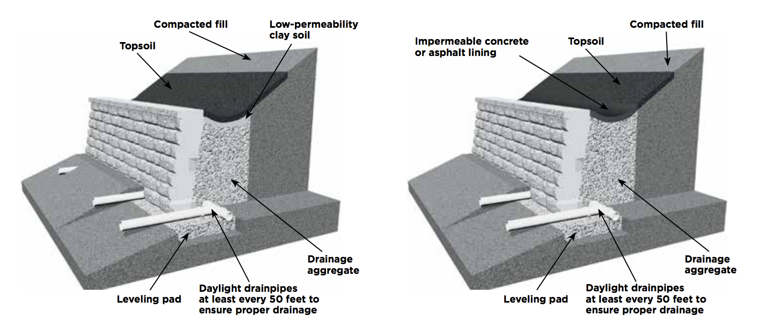
FINISH Course AND SURFACE DRAINAGE
• Protect the wall with a finished grade at the pinnacle and bottom.
• To ensure proper water drainage away from the wall, utilize vi inches of soil with low permeability. This will minimize h2o seeping into the soil and drainage aggregate behind the wall.
SITE CLEANING AND RESTORATION
• Brush off the wall and pick upwards whatever debris left from the construction procedure.
• Notify the chore superintendent in writing of the project'due south completion and that it is ready for final inspection and acceptance.
• Planting vegetation in front and on top of the wall will help reduce the chance of erosion.
• Following these best practices for construction will ensure the successful installation of Ballast™ products.
Wall Patterns for Multipiece Retaining Wall Systems
WHEN TO USE A PATTERN
You can install the multipiece retaining wall system in a random blueprint using whatever combination of units. Just avoid vertical lines that span more than than ane foot in acme. If you are edifice a wall without geosynthetic reinforcement, use a pattern for inspiration or follow a pattern exactly. Pleasing random patterns can be built using an equal number of half dozen- and 3-inch-high blocks or using an equal foursquare footage of blocks in each size. These patterns are based on using an
equal number of blocks of each size in each height. When building a wall that includes geosynthetic reinforcement, using a pattern at the advisable spacing eliminates the demand to cut the geogrid. When using a design, begin at one edge laying the blocks as indicated. Install at least i repeat of the pattern to establish the pattern before proceeding to the side by side course.
SEQUENT™ PANEL INSTALLATION Design

ix-inch by 3-human foot installation pattern
This 9-inch-high past 3-foot-long installation blueprint uses an equal number of units of each face size to make a panel. This installation pattern is ane of many possible options. Others tin can be used for unlike appearances.
RANDOM-Wait INSTALLATION PATTERNS

24-inch by 9-foot installation pattern
This illustrates a 24-inch-loftier past 9-human foot-long repeating installation pattern. The installation pattern uses an equal number of units of each face up size. When your plan requires geogrid, this installation pattern is ideal because it eliminates cutting if the geogrid is at 24 inches.

eighteen-inch by 6-foot installation pattern
This illustrates an 18-inch-high by 6-foot-long repeating installation blueprint. The installation pattern uses an equal number of units of each face size. When your plan requires geogrid, this installation design is ideal because it eliminates cutting if the geogrid is at 18 inches.

12-inch by ix-pes installation blueprint
This illustrates a 12-inch-high by ix-foot-long repeating installation pattern. The installation blueprint uses an equal number of units of each face size. When your programme requires geogrid, this installation pattern is platonic because it eliminates cutting if the geogrid is at 12 inches
Capping a Wall
Xl™ CAP Direct WALL
The 40™ cap must be laid alternately, curt and long faces, for a straight line. Always offset capping from the lowest elevation. One time caps are aligned, caps should be glued in place using a concrete agglutinative.
CURVES*
Lay out the cap units side by side with same confront facing out (long faces for outside curves; short faces for inside curves). If there's a need to accommodate for project'south radius, make cuts at least every other cap every bit needed for the nearly
pleasing aesthetic.
• Minimum radius with 40™ cap: ii'2"

xc-DEGREE CORNERS
Saw-cut two caps to achieve a 45-degree mitered corner.

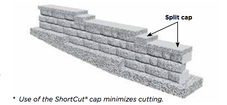
SHORTCUT CAP STRAIGHT WALL
The ShortCut® cap must exist laid alternately, narrow (N) and (West) wide faces, for a direct line. E'er commencement capping from the lowest elevation.

CURVES
Lay out the cap units side by side with same confront facing out (broad faces for exterior curves; narrow faces for inside curves). Occasional cut of some pieces may exist necessary.
• Minimum radius with ShortCut® cap: vii'half dozen"

ninety-DEGREE CORNERS
Identify ii caps together. Mensurate i½ inches from corners as shown. Utilize a straightedge to connect measurements and draw a line. Carefully cutting along the line to preserve both sides of the cut. Flip pieces "C" and "D" over to create corner.

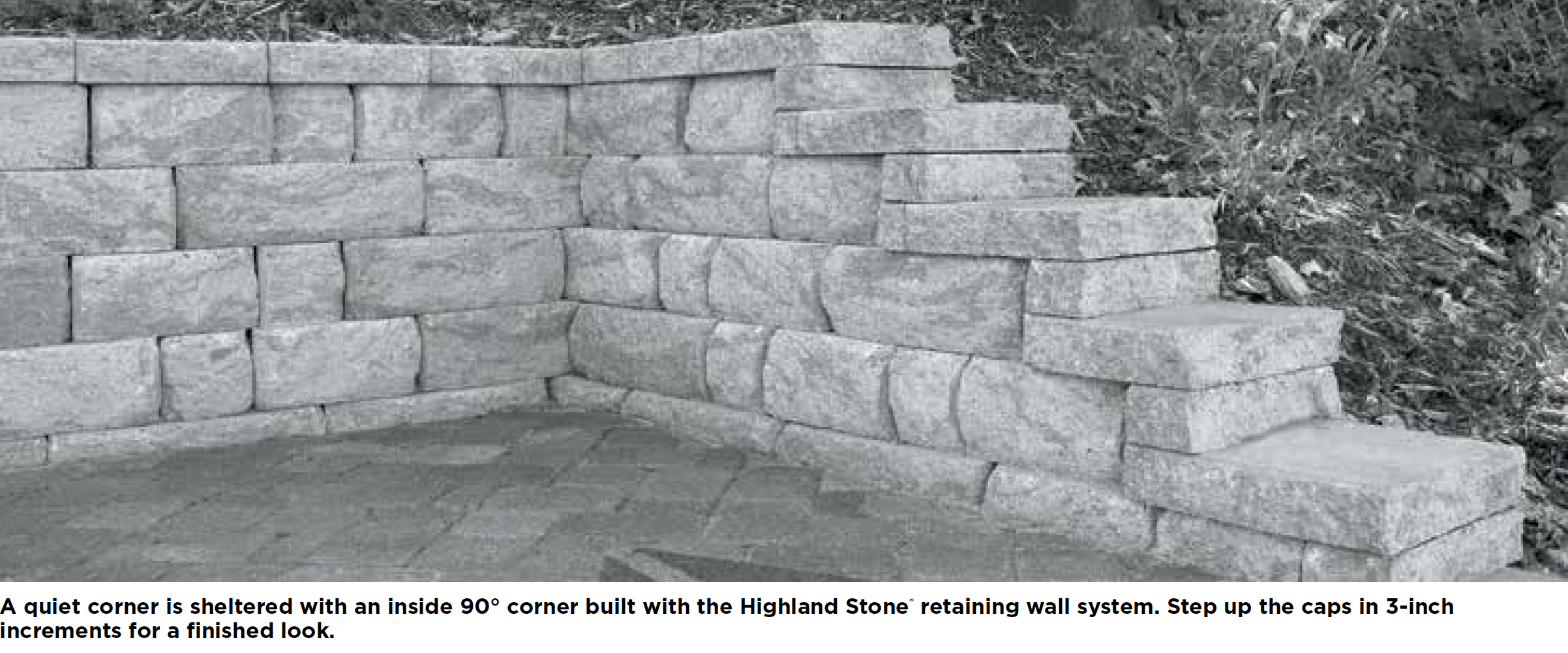
40™ CAP OR SHORTCUT® CAP STEPPING Up CAPS
If the wall pinnacle changes, caps can exist stacked where the wall steps upwardly. Begin laying caps at the lowest top change and work your way toward the next step upward. Divide* a cap unit to fit. Place the split unit directly on top of the capped portion of the wall with all 3 split up faces exposed.
FINISHING
Afterward layout is complete and caps are saw-cutting or divide to size, carefully place physical adhesive on wall top form and then place caps.
** To split a block, use a hydraulic splitter or split manually past using a hammer and chisel to score the block on all sides. Pound the chisel on the same line until the block splits. If partial unit sides are not exposed, utilize a circular cut-off saw with a masonry bract to attain a tighter fit.
Stepping Upward the Base, Abutting an Existing Structure and Capping a Column
STEPPING Upward THE BASE LOWEST Signal
Walls built on a sloping form require a stepped base. Begin excavation at the everyman point and dig a level trench into the slope until it is deep plenty to suit the base material and one entire block.
Pace-UP
At this point, step up the height of i block and begin a new section of base trench. Keep to footstep-up as needed to top of gradient. E'er bury at least one full unit at each step.

ABUTTING AN EXISTING Structure
Kickoff COURSE
Begin with the offset block side by side to the wall and place the first course. Identify filter fabric behind the beginning two large units and extend information technology two feet along the existing structure.
Second Grade
Build the 2d course with standard installation techniques. A split unit is shown, just may not be necessary in every installation. Extend filter material to the top edge of the final course. A condom membrane may be placed betwixt the units and a non-physical wall to foreclose moisture damage to the structure.

CAPPING A COLUMN
At that place are numerous ways to cap a cavalcade. You can use the Ballast™ column cap, cap units, unmarried-piece units or natural stone. Using an Forty™ cap—This capping handling requires eight XL cap units. Each unit is cut as shown. Top with the v-inch square coupon. Employ concrete adhesive to glue all pieces when cap is complete.

** To split a block, employ a hydraulic splitter or split manually by using a hammer and chisel to score the block on all sides. Pound the chisel on the same line until the cake splits. If partial unit of measurement sides are not exposed, use a circular cut-off saw with a masonry blade to reach a tighter fit.
Daylighting Drainage and Drainage Swales
DAYLIGHTING DRAINAGE FIRST COURSE
To daylight drainpipes through a wall face, put them on compacted leveling pad aggregate placed behind the first course. Infinite these drains not more than 50 feet apart. Split ii inches off the forepart of ii adjacent large units to provide infinite for the drainpipe to exit through the face up.
SUBSEQUENT COURSES
Build this and remaining courses using standard construction techniques. Tip: To daylight through slope, run across Drainage Swales.

DRAINAGE SWALES
Design and operation of most retaining walls are based on keeping the reinforced zone relatively dry out. Appropriate drainage swales to help control water should be designed into the wall construction program
Steps in a 90° Wall
Base COURSE
Thoroughly compact the leveling pad. Lay out the base course according to the wall design. Place step units first, working from the heart to each side. It is very of import to backfill and meaty behind and along the sides of each course of pace units.

Kickoff Footstep COURSE
Identify the first grade of stride units directly on tiptop of the base course so there is no setback. Stagger them from the previous course and glue in place.

Second Footstep COURSE
Add together the 2nd class of steps, staggering them over the previous course to maintain running bail. Overlap the previous course past 2 inches and mucilage to the lower course. Identify and meaty soil fill prior to installing the next class.
SECOND WALL Form
Build the second class of the wall.

Third Stride Class
Get-go in the center, add together the third form of steps, lining upwards the units with the first form. Overlap 2 inches and mucilage in place.
ADDITIONAL COURSES
Build the third class of the wall. Echo wall and step courses until the wall is finished. Drainage tip: Drainpipe tin be placed behind the lowest step units at grade or behind each wall side by side to the steps.

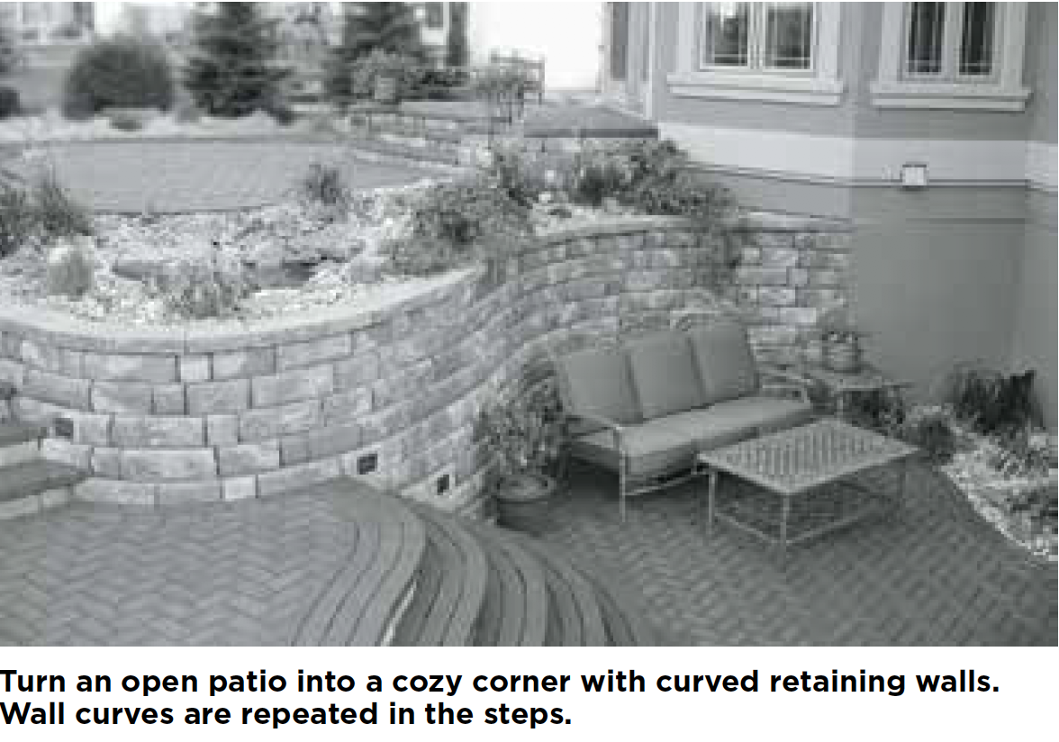
Steps in a Curved Wall
BASE Form
Thoroughly compact the leveling pad. Lay out the base grade co-ordinate to the wall design. Place stride units starting time, working from the center to each side. It is very important to backfill and meaty behind and along the sides of each class of footstep units.

FIRST Footstep COURSE
Place the start course of step units direct on tiptop of the base of operations course so there is no setback. Stagger them from the previous course and glue in place.

2nd Footstep Course
Add the second course of steps, staggering them from the previous grade to maintain running bond. Overlap the previous course past 2 inches and glue to the lower grade. Place and compact soil fill prior to installing the side by side course.

SECOND WALL COURSE
Place a block nigh the 2nd course of steps, maintaining running bond with the base of operations course. Measure and cut a cake to fit the space remaining betwixt the pace unit of measurement and the adjacent form of the wall. Identify the unit in the wall, making sure that both vertical edges fit tightly confronting both the step and standard unit. Remove the rear lip on the blocks when necessary, and angle the blocks flush with the face up of the previous course. Glue in identify with a physical adhesive.

Boosted COURSES
Beginning in the center, add the third course of steps, lining upwards the units with the beginning course. Overlap 2 inches and gum in identify. Echo step and wall courses until the wall is finished. Drainage tip: Drainpipe can be placed behind the everyman step units at grade or behind each wall adjacent to the steps.


Outside Curves
Calculate THE RADIUS
When building an outside curve, brainstorm by computing the radius of the peak course. This will be the smallest radius in the wall and must not be less than the minimum radius for the cake system used.
To summate the approximate radius of the height course: Add 1⁄4 inch to the setback of the block used. Multiply that amount by the number of courses in the finished wall. And then subtract the result from the radius of the base course. This number equals the calculated radius of the top course.

Base of operations COURSE
Bulldoze a stake into the basis at the desired center of the bend. Attach a string and rotate it in a circle around the stake to mark the radius in the soil. Align the back of the block with the curve and ensure level placement from side to side and front end to back.

ADDITIONAL COURSES
On each course, the lip of each block must be in contact with the back of the units below to ensure structural stability. The setback of the cake volition cause the radius of each class to gradually decrease and somewhen touch the running bond of the wall. To maintain proper running bond, use partial units as needed. One time a block is cut to size, glue it in place with a physical adhesive.


Outside Curves with Geosynthetic Reinforcement
Most retaining walls are designed assuming 100 percent coverage of the geogrid. When building an outside curve, the block edges of the geogrid will have gaps so that the dorsum edges don't overlap. In order to ensure 100 percent coverage, additional lengths of geogrid are used to fill those gaps on the next grade of blocks. To prevent slippage, don't overlap the geogrid on any given course.

Commencement COURSE WITH GEOSYNTHETIC REINFORCEMENT
Cut geogrid to the lengths specified in the wall plan. Lay sections of the geogrid within 1 inch of the face of the wall with the forcefulness direction perpendicular to the wall face. Avert overlapping the geogrid past separating each department.

SUBSEQUENT COURSES
Place the next class of blocks, marker their backs to place unreinforced areas. This footstep is important because when this course is backfilled, it'due south incommunicable to locate the unreinforced areas. Utilise the marked blocks as a guide, placing subsequent sections of geogrid to overlap the gaps left on the previous grade. This will ensure total geogrid coverage. Echo this procedure throughout the construction of the curve when geogrid is required.

Within Curves and Within Curves with Geosynthetic Reinforcement
Summate THE RADIUS
Cheque the wall plan to determine the radius of the base grade. This volition be the smallest radius in the wall and must non be less than the minimum for the block organization used.

BASE Form
Begin by driving a stake into the ground at the desired centre of the curve. Attach a string and rotate it in a circle effectually the stake to marker the radius in the soil. Align each block confront with the radius curve and ensure level placement from side to side and front to back.
Additional COURSES
On each course, the lip of each cake must be in contact with the dorsum of the units beneath to ensure structural stability. The setback of the cake will cause the radius of each grade to gradually increase and somewhen affect the running bond of the wall. To maintain proper running bond, use partial units equally needed. Once a separate unit is cut to size, glue in identify with a concrete agglutinative. Nearly retaining walls are designed assuming 100 percent coverage of the geogrid. When edifice an within curve, the dorsum edges of the geogrid will fan out, producing slight gaps. In order to ensure 100 percent coverage, boosted lengths of geogrid are used to fill up those gaps on the side by side course of blocks. To preclude slippage, don't overlap the geogrid on any given class.

First COURSE WITH GEOSYNTHETIC REINFORCEMENT
Cut geogrid to the lengths specified in the wall plan. Lay segments of geogrid inside ane inch of the face up of the wall, making sure that the forcefulness direction of each section is perpendicular to the wall face. Avoid overlapping the geogrid by separating each section.

SUBSEQUENT COURSES
Identify the next course of blocks, marking their backs to identify unreinforced areas. This step is important considering when this grade is backfilled, it'due south incommunicable to locate the unreinforced areas. Use the marked blocks every bit a guide, placing subsequent sections of geogrid to overlap the gaps left on the previous form. This will ensure full geogrid coverage. Repeat this process throughout the construction of the curve when geogrid is required.

Outside xc° Corners and Outside Curves with Geosynthetic Reinforcement
BASE Class
To build an outside ninety° corner, begin by splitting* a large block in half. Place this cake with both divide faces outward at the corner. Remove the rear lip so that the block lies apartment. Then lay the rest of the base form working from the corner cake out.
ADDITIONAL COURSES
Begin the 2d course with the other half of the big cake. Identify the second and third blocks on either side of the corner block. Once the corner block is in position, glue it in identify with a concrete agglutinative. Go on to alternate the corner cake orientation with each grade and always apply a concrete adhesive.

Starting time COURSE WITH GEOSYNTHETIC REINFORCEMENT
Brainstorm by checking the wall plan to determine geogrid lengths and elevations. Lay a section of geogrid well-nigh the corner of the wall, ensuring that it's placed within 1 inch of the face of the block and running forth the dorsum of the adjoining wall.

SUBSEQUENT COURSES
Lay the adjacent class of cake, backfill and compact. When installing the next section of geogrid, place within 2 inches of the face up of the block and running along the back of the adjacent wall.
* To split a block, employ a hydraulic splitter or split manually by using a hammer and chisel to score the block on all sides. Pound the chisel on the same line until the block splits. If partial unit sides are not exposed, use a circular cut-off saw with a masonry blade to achieve a tighter fit.


Inside ninety° Corners
BASE COURSE
To create an within 90° corner, begin by placing a block at the corner. Then lay a second block perpendicular to the starting time and continue laying out the residuum of the base grade working from the corner out. Remove the rear lip so the cake lies flat. Make sure to construct the base course according to standard site prep and installation procedures described earlier.
ADDITIONAL COURSES
On the 2nd course, place all blocks on bond forth one side of the corner. Once the 2nd grade of one wall is established, brainstorm the second course of the adjacent wall. Block placement in the corner should alternating management with each succeeding course.

Inside 90° Corners with Geosynthetic Reinforcement
FIRST COURSE WITH GEOSYNTHETIC REINFORCEMENT
Begin by checking the wall programme to make up one's mind geogrid lengths and elevations. Cutting geogrid to the lengths shown in the wall program, paying attention to the geogrid strength direction.
Side by side, determine the proper placement of the geogrid past dividing the proposed height of the wall past four. This represents the altitude that geogrid should extend beyond the forepart of the adjoining wall. Measure this altitude from the front of the bordering wall, and brainstorm the geogrid placement hither. Make sure the geogrid is placed within i inch of the face of the wall and runs along the dorsum of the bordering wall.

Place the next department of geogrid on the adjoining wall. The geogrid should non overlap and should prevarication affluent with previously placed sections. One time geogrid is in identify, the next courses of block can be installed.

SUBSEQUENT COURSES
The first department of grid on these courses is placed using the same formula that determines placement in front end of the bordering wall.

Alternating the geosynthetic reinforcement extension on each course where geogrid is required. Place the adjacent department of geogrid on the bordering wall. The geogrid should not overlap and should prevarication flush with previously placed sections. In one case geogrid is in identify, the next courses of cake can be installed.

H2o Applications
With correct design and construction, Anchor™ products tin can be successfully installed at the edge of h2o channels, river banks and drainage ditches. The terminal design of the wall is affected by various factors, including the movement and velocity of the next water, erosion and scour, the direction of water travel to the wall, the risk of flooding, equally well as the soil and basis conditions where the wall is being congenital. A qualified engineer should always exist consulted to determine the effect of water on the wall and to blueprint a wall that takes all these factors into account. Consult a qualified engineer before design, construction and installation take place, and follow the engineer'south design.

BASE COURSE
Place a filter fabric with actress length in front of the wall. Install the leveling pad and the base class of cake, including drain tile and drainage aggregate. Wrap the extended filter fabric up along the face of the base course. Identify soil make full in front of the wall and compact. Install another department of filter fabric in forepart of the wall to protect against erosion. Cover the cloth with a minimum of 3 inches of sand. Install larger stones, such as riprap, to concord it in place.
NEXT COURSE
Continue constructing the wall. Drainage is vital. To forestall bottleneck of the drainage amass and drainpipe by finegrained soils, a filter fabric is installed to separate the drainage amass from the reinforced soils.
Boosted COURSES
Continue these steps until the wall is complete. The last department of filter fabric should cover the drainage aggregate and sew together against the dorsum of the top form of cake. Add fill soil and compact.

Terraces and Fences
Contained TERRACED WALLS

For each wall to be independent of others, it must exist built using a 2:1 ratio – the upper wall must be built a altitude
away from the lower wall of at to the lowest degree twice the height of the lower wall. In addition, the upper wall must also be equal to or less than the acme of the lower wall. Exceptions to this
full general rule include weak soil conditions or where slopes be to a higher place, below or between wall locations. For case, if the lower terrace is four feet alpine, the distance between the terraces must be at least 8 anxiety and the upper wall must not be higher than 4 anxiety. Drainage is vital to maintaining stable, long-lasting terraced walls. Drainpipe must be installed and so that the water is directed around or under the lower wall (never place the bleed outlet for the upper wall above or behind the lower wall). For more than detailed information almost drainage, come across Daylighting and Drainage Swales on folio 9.
DEPENDENT TERRACED WALLS

When the distance between the lower and upper walls is less than twice the meridian of the lower wall, the walls become structurally dependent on each other. In this state of affairs, information technology is of import to take global stability into account, incorporating additional geogrid– and longer layers – into the wall programme. In improver, structurally dependent walls require fifty-fifty more than excavation, backfill and time. So plan ahead. Be sure to check the wall program for specific requirements. For structurally dependent walls, consult with a qualified engineer.
FENCES

Know the dimensions of the fence to determine the placement of the sleeves. Provide at to the lowest degree one inch clearance between the inside of the sleeve and the outside of the post, and let for mortar and grout. Install the sleeves according to the wall plan during the structure of the wall. If the debate is at least 3 feet behind the wall, generally no boosted geogrid is required. If the fence is installed within iii feet, in that location may exist some load transferred to the wall from air current, snowfall or pedestrians. Additional geogrid around the debate sleeves may be needed. Grout the fence post into the sleeve after the wall is congenital.
Freestanding Wall Installation Instructions
PREPARE LEVELING PAD
Excavate for the leveling pad. To conform the Torpedo® base cake the trench should exist 24" wide and 12" deep; otherwise, the trench should be a minimum of 21 inches wide and should exist 6 inches deeper than the block. See Diagram one. Create a leveling pad of compacted base material that extends a minimum of 6 inches in forepart of and 6 inches behind the wall units. This pad should besides exist at least 6 inches deep afterwards compaction.

BASE COURSE*
In one case the pad is compact and level, brainstorm placing the units. Centre the units on the pad. The ends of the units should exist in contact. The base grade must be buried beneath grade and should be included when calculating total wall height.


Edifice THE WALL
Units can be placed in any order to grade an aesthetically pleasing layout. The simplest is one that incorporates big, medium and small units. The units should be installed so the ends are in complete contact with each other. Think to keep the wall on bond by placing units in a staggered relationship to the course beneath. Echo this process to complete the wall. Mucilage the tiptop two courses and caps in identify with a physical adhesive.

Catastrophe A WALL
Separate a large unit of measurement into pieces sized equally needed. Do not utilise pieces smaller than six inches wide. If needed, cut the second-to-concluding piece and make the last slice the appropriate size. Smaller pieces should be glued into identify with a physical adhesive. After splitting the end piece, utilize a hammer and chisel to create a rounded appearance to match the manufactured split blocks.

INSTALLATION PATTERN
6" Multipiece Freestanding Wall System Installation Pattern

Freestanding Wall Installation Instructions
STRUCTURAL Design ELEMENTS
Structural design elements must exist used if a freestanding wall is more x anxiety long. Structural blueprint elements include
• curved walls
• freestanding wall jog
• 90° corner
• columns
CURVED WALLS
Add stability and a natural flow to walls with curves. While units can be turned somewhat, information technology may be necessary to make cuts with a concrete saw or splitter. Every bit a rule, the smaller the units, the tighter the radius. Conversely, the larger the units, the larger the radius. Utilise approximately the same number of units for each form. The approximate minimum radius the system can turn, using all 3 pieces without cut, is iii.75 feet measured to the exterior confront of the wall.

FREESTANDING WALL JOG

Jogs are used to break up directly lines and add stability to walls. Carve up units as needed. Utilise hammer and chisel to round split up faces. Mucilage all courses of jog with a concrete adhesive.

90° CORNER

To create a ninety° corner in a directly wall, brand a third side to a big unit by splitting it to the appropriate dimension. Use just large units to assure connecting units are on bond. Alternate the direction the units face with each course. Round the split ends with a hammer and chisel. Mucilage all corner courses with a concrete adhesive.

Construction Details for Multipiece Freestanding Wall Systems
COLUMNS
When used with a freestanding wall, a column increases wall stability. Placing fixtures on columns is also a great way to incorporate lighting. Columns can be located in the center or at the terminate of a wall. The open up infinite in the centre of a column permits reinforcement or electrical wiring if needed. The column leveling pad should extend half dozen inches beyond each cavalcade edge and be at least half-dozen inches deep after compaction.

COLUMN AT Cease OF WALL—CENTERED

To build columns at the end of a wall, cut 1 cavalcade unit in one-half for the second, fourth and additional even-numbered courses. Stack cavalcade units in a rotating pattern for each class so that the bond is staggered. One column unit of measurement half is used every 2 courses. Glue each form of column units with a concrete agglutinative. Integrate wall into column as shown to increase stability.
CAPPING A COLUMN AND A WALL

COLUMN AT Terminate OF WALL—First

To build a cavalcade at the finish of a wall, stack iii column units as shown for the base class. For the 2nd course, use column units, stacking in a rotating pattern. Gum each course of units in the column with concrete agglutinative.

WALL THROUGH Column

On the first course, use complete cavalcade units to beginning the column and cut the wall units to fit. On the 2nd grade, cut two column units in half to make full in the corners. Continue construction past alternating courses. Mucilage all column courses with a concrete adhesive.

Construction Details for Multipiece Freestanding Wall Systems
Column IN RUNNING WALL

Columns add stability and elegance to a wall. They are located on one side of a wall. To build a column, stack column units in a rotating design for each course. Cut wall units as indicated. Mucilage each grade of units in the cavalcade with a concrete adhesive.

90° CORNER AT Column

Frequently, a 90° turn is made at a column. To build this column, cut i column unit per class. Stack column units in a rotating pattern for each form. Glue each form of column units with a concrete adhesive.

SMALL COLUMN IN WALL

There are times when a column of a different size is needed. To build a smaller cavalcade in the running wall, you will demand to split a medium stretcher unit for the first form. Dissever it and so that the
pieces, combined with another medium unit, equal 18 inches. Identify the units parallel to the wall on the prepared leveling pad. For the second course, split a large stretcher unit and a medium stretcher unit of measurement and then that they equal 18 inches. Dissever a second fix of big and medium units to make a second 18-inch section. Insert these units perpendicular to the wall equally shown. Mucilage all courses. Round the split ends with a hammer and chisel.

SMALL COLUMN AT END OF WALL

To build a smaller cavalcade at the cease of a running freestanding wall, you will need to dissever four stretcher units for the beginning course. Split a big and medium unit so they equal 18 inches. Split a second prepare of units to brand a second 18-inch section. Insert the unit of measurement sets perpendicular to the wall on the prepared leveling pad. For the 2d course, eye a medium stretcher unit over the base units every bit shown. Divide some other unit to maintain a staggered bond. Round the separate ends with a hammer and chisel. Glue all units in the column with a concrete adhesive.

Source: https://www.anchorwall.com/10596-installation-guide
0 Response to "Place Freestanding Wall Unit Not Again Wall"
Post a Comment